← All subprojects

Subproject · Detector readout

PCB anodes: timing detectors with high signal fidelity.

Passive, capacitively coupled readout anodes for microchannel plates and channeltrons, built on segmented polyimide laminates — the technology published in Kendler et al., Rev. Sci. Instrum. (2026).

Our approach

From FR4 problems to polyimide laminates.

Regular PCBs in vacuum

  • Outgassing of volatile components
  • Not suitable for high-frequency signals out of the box
  • Limited temperature range — no bake-out possible

Our segmented polyimide laminates

  • No outgassing
  • High breakdown-voltage capacitor embedded in the board
  • High-frequency compatible material
  • Temperature tolerance for bake-out
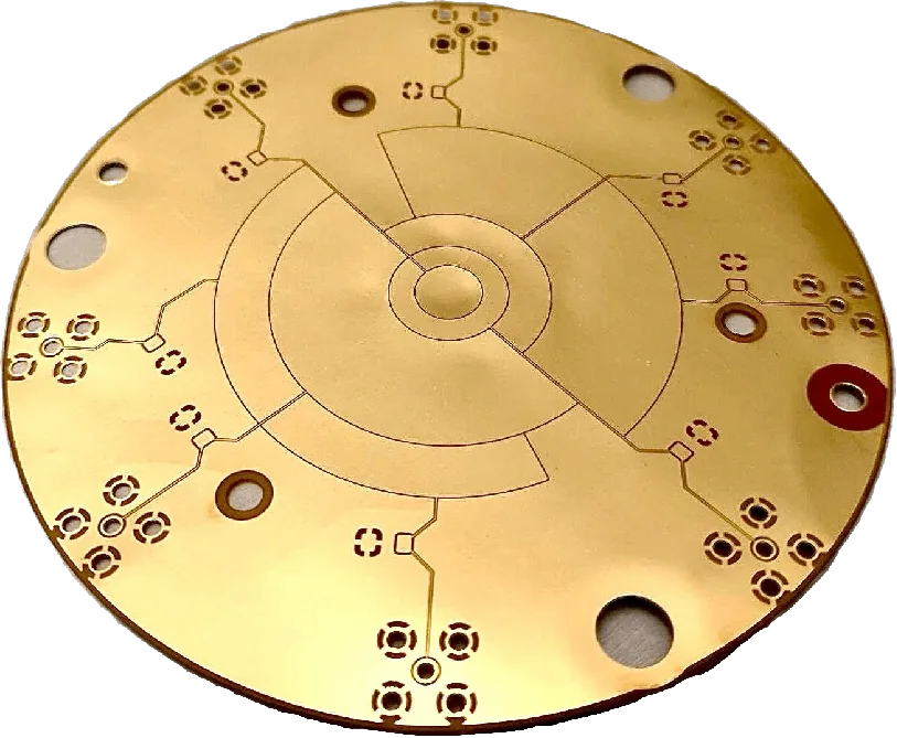
Gold-plated segmented polyimide anode board
A segmented polyimide-core anode: copper circuitry on a thin, UHV-compatible laminate.

50 Ω transmission lines

Impedance-matched, EMI-shielded lines printed directly on the board.

Embedded capacitor

High-voltage capacitive out-coupling built into the laminate stack.

High-bandwidth connectors

On-board SMA mounts for 2 GHz coaxial cables.

Segmented pickup patches

Arbitrarily shaped signal pickup segments for parallel readout.

Engineering

Four UHV readout problems,
solved on one laminate.

UHV / high-voltage / HF challenge Our solution
Stiff, brittle insulation materials such as ceramics — unreliable mounting in tight spaces Flexible laminates with high-voltage capacitive out-coupling included — flexible for different applications
Unshielded UHV wires unsuitable for HF signal transmission — high AC noise floor Printed 2D transmission lines with 50 Ω impedance — ultralow signal noise
Discontinuous line impedance at non-standard cable connections — signal ringing On-board SMA connectors and 2 GHz coax for constant 50 Ω matching — no signal ringing
HV feedthroughs typically not high-bandwidth compatible — damping HV capacitive out-coupling embedded in the design — high signal amplitudes
  • Higher-bandwidth signal read-out
  • Lower noise floor on the transmission line
  • Higher signal-to-noise ratio
Star-shaped flexible polyimide anode with five arms
Flexible designs — e.g. for a CF40 flange or tube layout — with flexible transmission lines for tight spaces.

Results

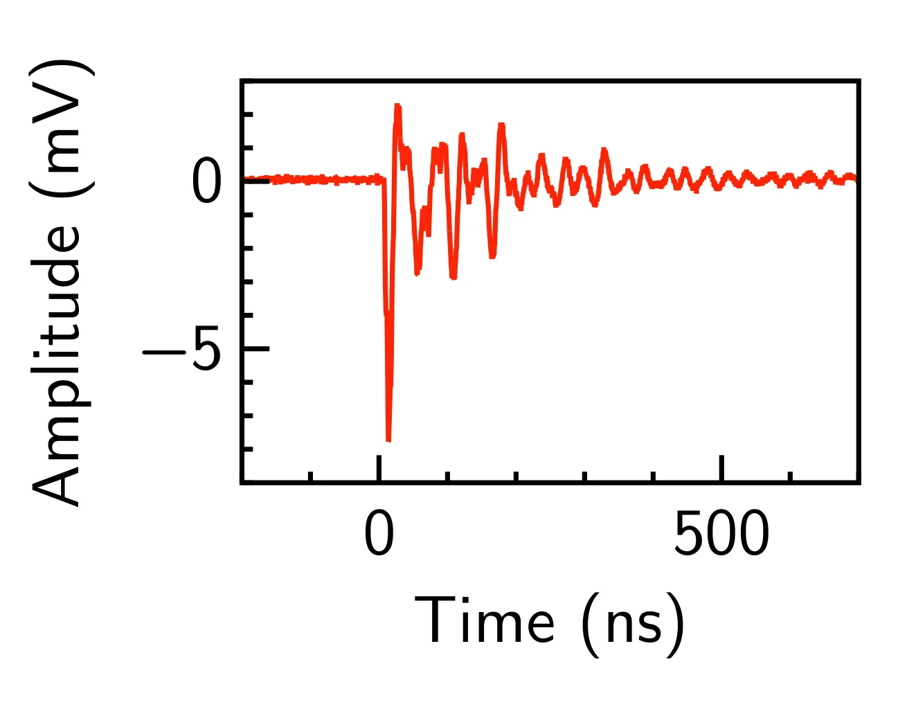
From 500 ns of ringing
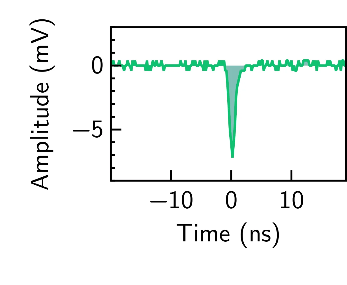
to a clean 5 ns pulse.

Signal of a standard timing anode: a pulse followed by 500 nanoseconds of ringing
Standard timing anode — 500 ns per pulse; the count rate must stay ≪ 1 MHz to avoid overlap and pile-up.
Signal of the PCB anode: a single clean 5 nanosecond pulse
Our PCB anode — 5 ns per pulse; count rates > 1 MHz are easily possible. Note the different time bases.
≪ 1 nssignal rise time
< 100 pssignal jitter
80–100 psTOF stop-time resolution — world record
> 1 MHzcount rate — real-time process control with an RGA
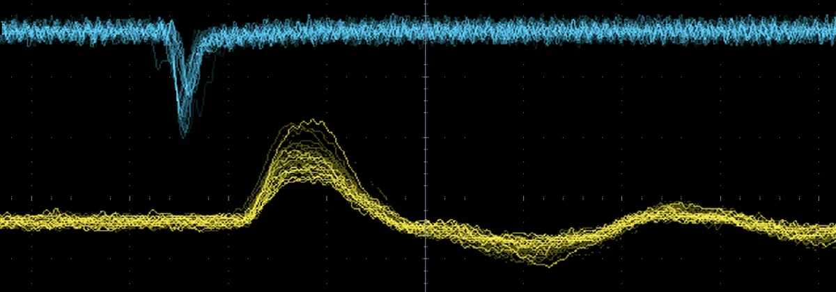
Overlaid oscilloscope traces comparing the 3 nanosecond PCB anode pulse in blue with a 10 nanosecond standard metal anode pulse in yellow
Overlaid oscilloscope traces: our PCB anode (blue, ~3 ns) against a standard metal anode (yellow, ~10 ns). The steeper edge shrinks the discriminator triggering spread — for a target mass resolution of m/Δm ≈ 200 the stop-time spread σt must stay below 1 ns, especially for small atomic masses and short TOF chambers.
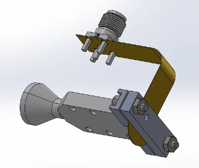
CAD model of the flexible PCB anode mounted on a channeltron electron multiplier
CAD model of the flexible PCB anode mounted on a channeltron — the first test was successful.

Beyond the MCP

Fits a channeltron.
Fits tight spaces.

  • Higher TOF resolution — higher mass resolution
  • Higher count rates — faster spectrum acquisition
  • Higher sensitivity — detect trace amounts
  • Segmented MCP anode — measure faster, in parallel
  • Fits a channeltron, fits tight spaces

Faster, cleaner detector readout
for your instrument.

The segmented anode is published and running — as an MCP timing anode and on a channeltron. We are looking for partners who want this signal fidelity in their own detectors.